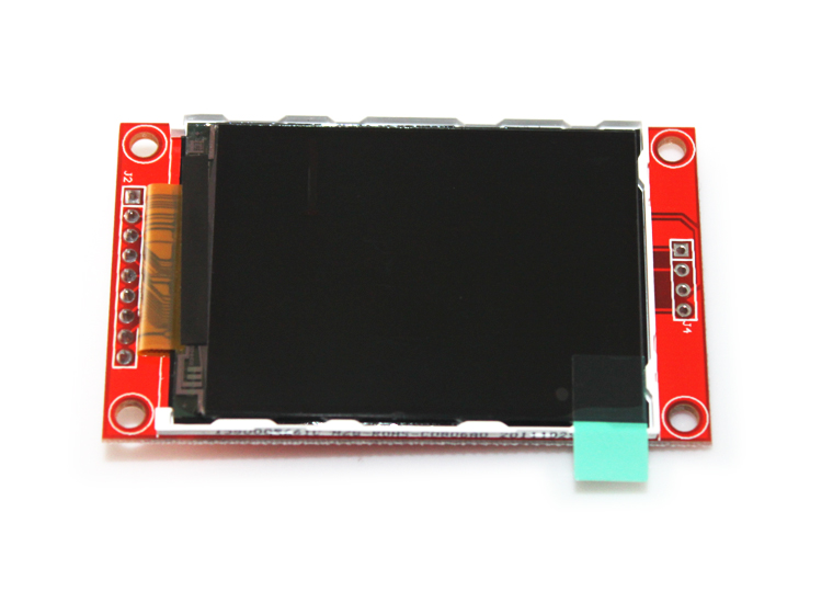
Arduino and the QVGA 2.2" TFT SPI screen
 I went through all the struggles everybody else seems to be going through to get this screen connected to my Arduino Nano. I had the 5V to 3.3V voltage conversion problem, and the "only works with software interrupts" problem which makes the display run slow. The solutions are not complicated but not very wel documented. Until now.
Step 1: It's a 3.3V screen Before connecting the screen to your Arduino, it's important to know that this screen uses 3.3V logic. That means that connecting your Arduino to it will likely ruin the screen. If you're not using the CF cardreader on the screen then the communication is one-way to the screen. Converting your 5V outputs to 3.3V is really simple, all you need is a couple of cheap 1N4148 diodes and a few resistors (for alternatives, see below). Connect your screen as follows:
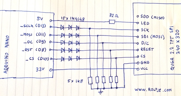
Please make sure you wire all connections in this schematic.
Step 2: Hidden pins in the code The Adafruit ILI9340 library contains some examples on how to get the screen running. You'll need the SPI and Adafruit_GFX libraries too, as shown in the header of the examples. Let's look at a little code that alternates the screen between black and white:
[sourcecode language="cpp"] /*
- Example code to make the TFT alternate
- between black and white using hardware SPI: */ #include "SPI.h" #include "Adafruit_GFX.h" #include "Adafruit_ILI9340.h"
// TFT pin mappings for UNO/NANO #define _sclk 13 #define _miso 12 #define _mosi 11 #define _cs 10 #define _dc 9 #define _rst 8
// Use hardware SPI Adafruit_ILI9340 tft = Adafruit_ILI9340(_cs, _dc, _rst);
void setup() { tft.begin(); tft.fillScreen(ILI9340_GREEN); }
void loop() { tft.fillScreen(ILI9340_BLACK); tft.fillScreen(ILI9340_WHITE); } [/sourcecode]
Note that there is something funny going on here. The constructor for the Adafruit_ILI9340 object only has _cs, _dc, and _rst as parameter. Initially I thought "Great, only 3 connections to the display!". Alas, this is not the case. You still need to wire the _sclk and _mosi port to the display. The _miso port can be left out, but you can't use it for anything else on the Arduino side because the library seems to be accessing it.
If you have your connections correct and upload the example above to your Arduino, you should see your screen continuously alternate between black and white. You will be able to see the drawing of the screen, but it should not take more than 1 second to fill the whole screen. If it takes more than a second to fill the screen, you're likely using the software SPI method. Check the code and the connections again.
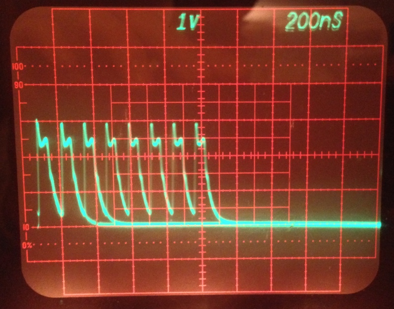
This is how the data on the _mosi pin looks on a Tektronix 7623A oscilloscope when drawing graphics on the TFT screen. It's not a perfect square because of the capacitance of the diodes, but the difference between high and low states is good enough and the slope is just fast enough so that the display sees all the bits that are sent to it:
Alternative 5V to 3.3V conversions:
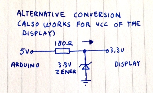 If you don't have enough diodes, you can use zener diodes as shown on the right. I have not tested this on my screen but it should give you similar results, and saves you a few components.
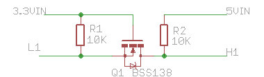
A much nicer, two-way level conversion enables you to connect the _miso port to talk to the CF Card Reader. You can make this with an N-Channel MOSFET. Check Andrew's blog on how to use an N-channel FET to do the conversion:
If you need more speed or less components, you can also check out Maxim's range of level conversion ICs.
Have fun!