Better modulation for the Baofeng UV-5RA
 Undoubtedly the Baofeng UV-5Rx delivers a lot of radio for your buck. However some models in the range have a bad reputation for the transmitted audio sounding soft and muffled.
In 2013, Remco PA3FYM obtained the schematics of the radio and devised a modification where transistor Q17 of the VOX is re-purposed as preamplifier in the microphone audio circuit. It works wonders for your radio. For people needing a bit more visual guidance, below is a walktrough of how I did this to my Baofeng UV-5RA.
On the left you find the original schematics of the microphone and vox circuits. On the right, I've marked the modifications we're about to do in red.| [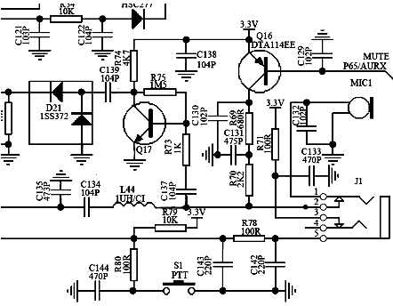 ](uv5r-schema-before.png) | [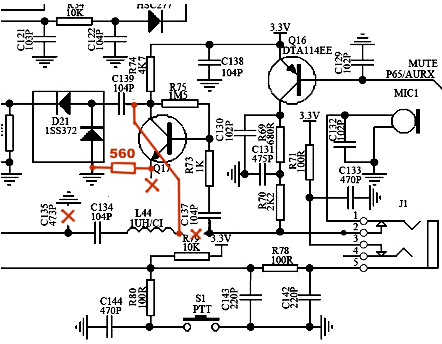 ](uv5r-schema-after.png) |
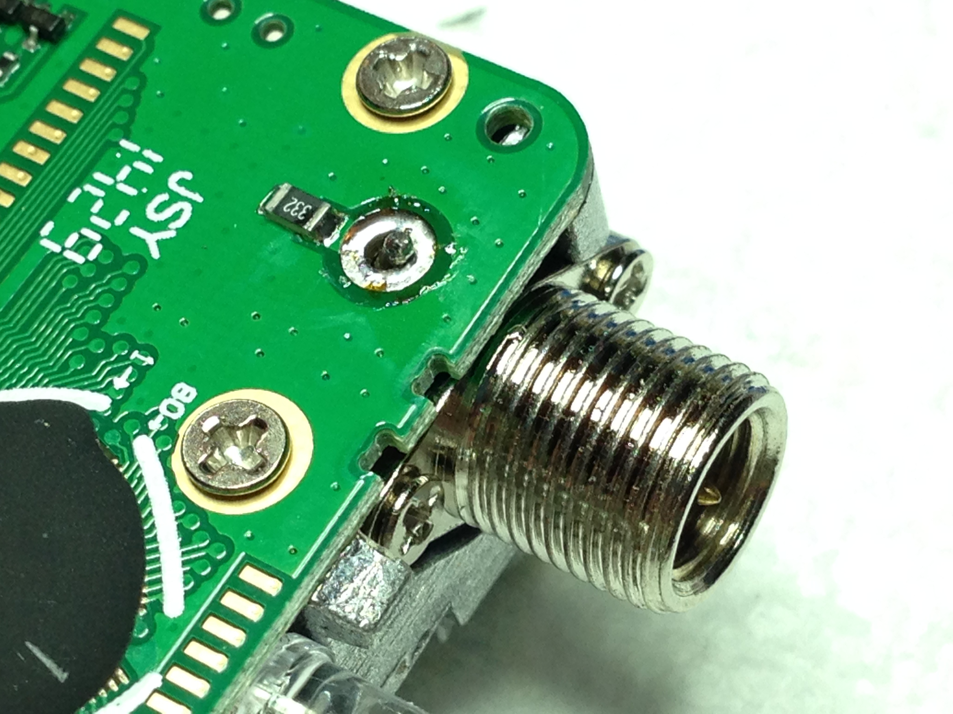
Remember: the radio comes apart without force. If you feel something is not giving, look for solder joints or screws you missed. For easy removal of the display, I used solder wick to remove the solder on the backlight connections:
 Just to be sure I desoldered the antenna connection but you can also unscrew the antenna connector and carefully force it over the aluminum ridge.
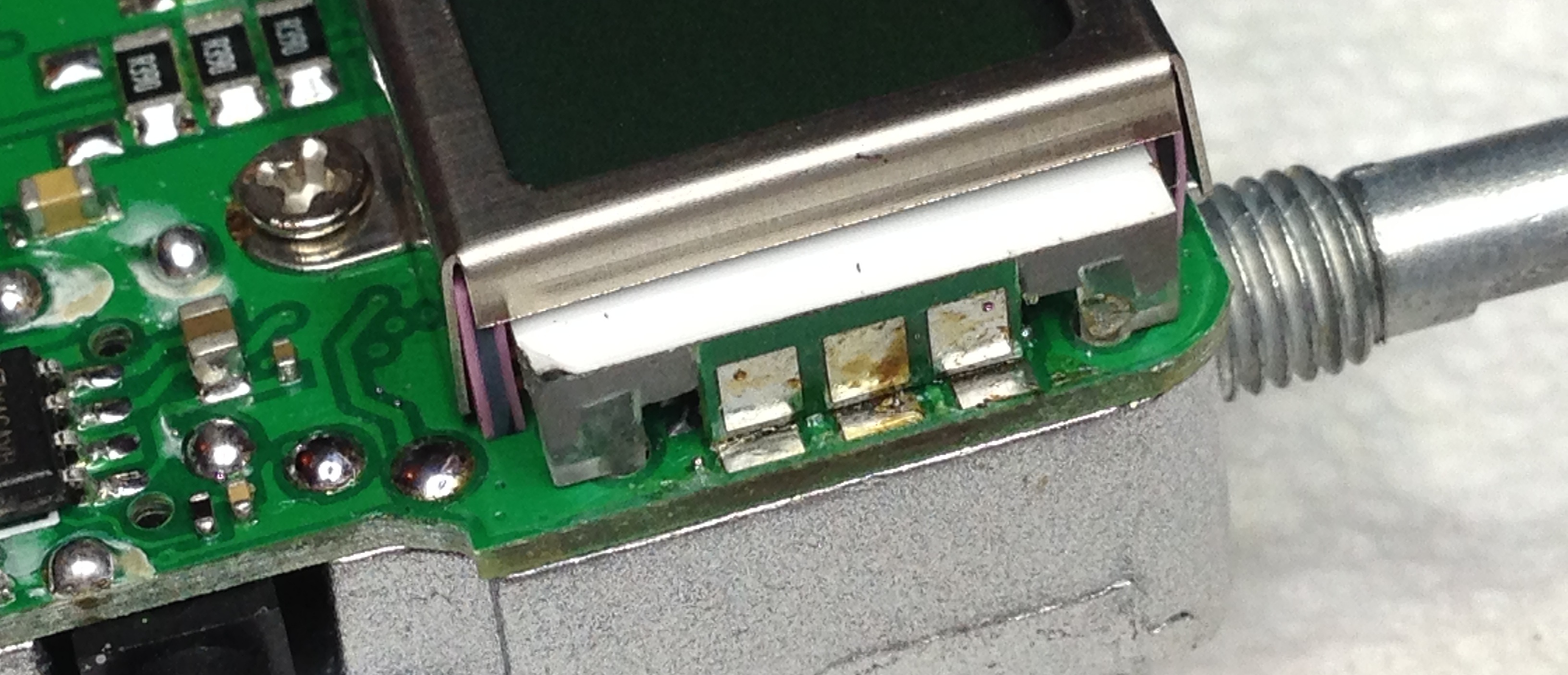
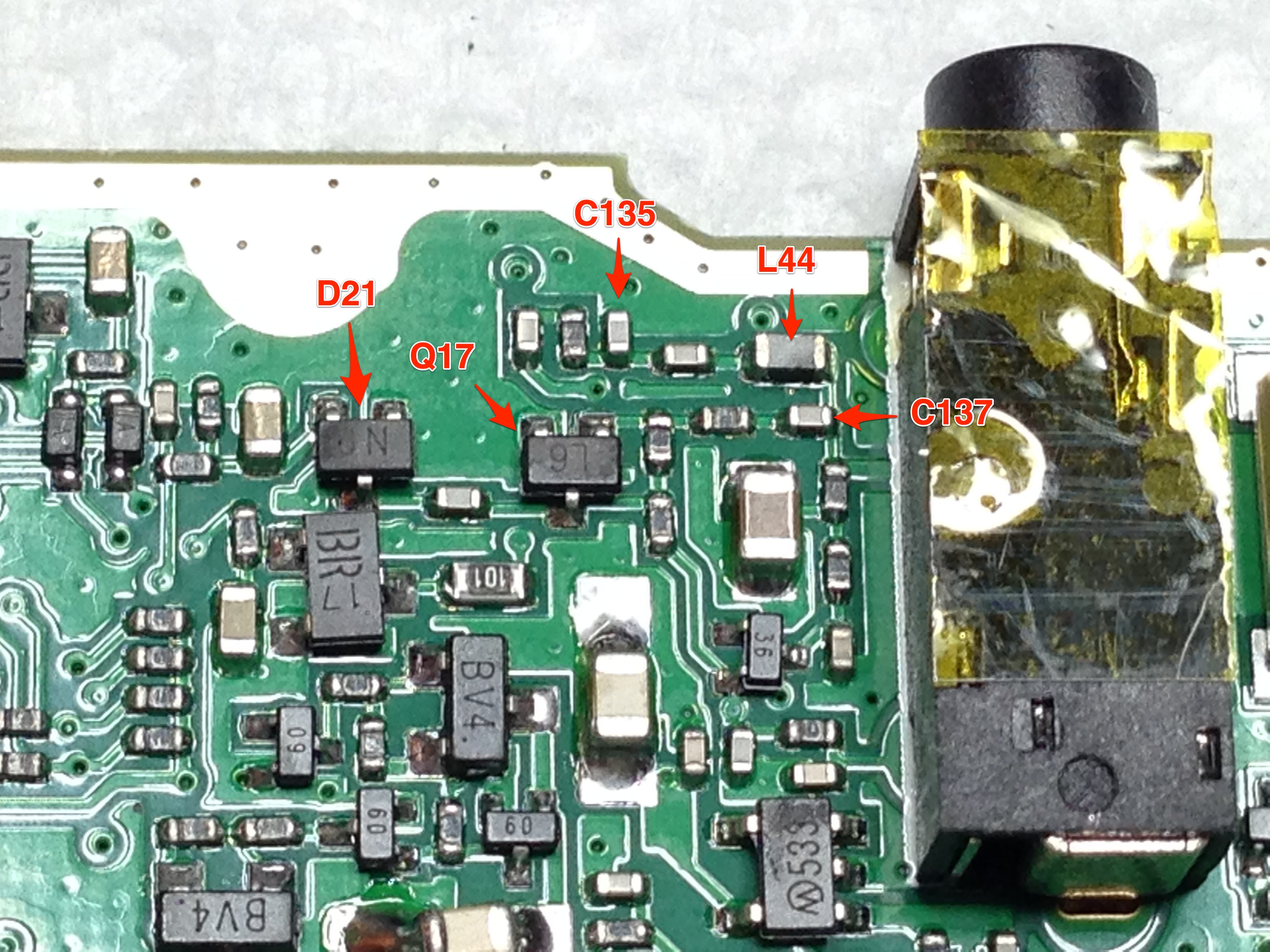
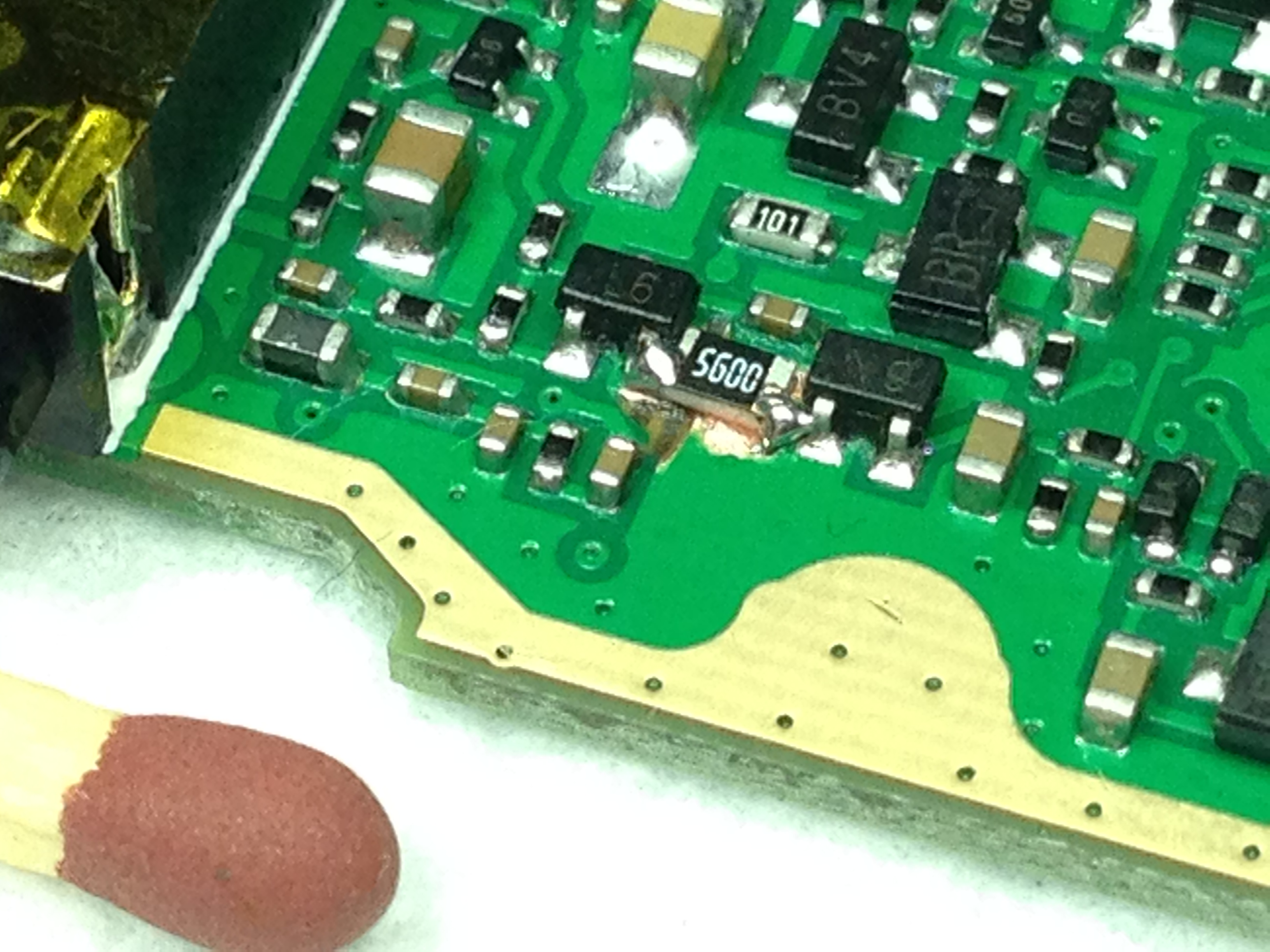
**Step 2: Locate components **Locate the components in the schematic on the printed circuit board. Use a multimeter to ensure yourself that you are looking at the right components:
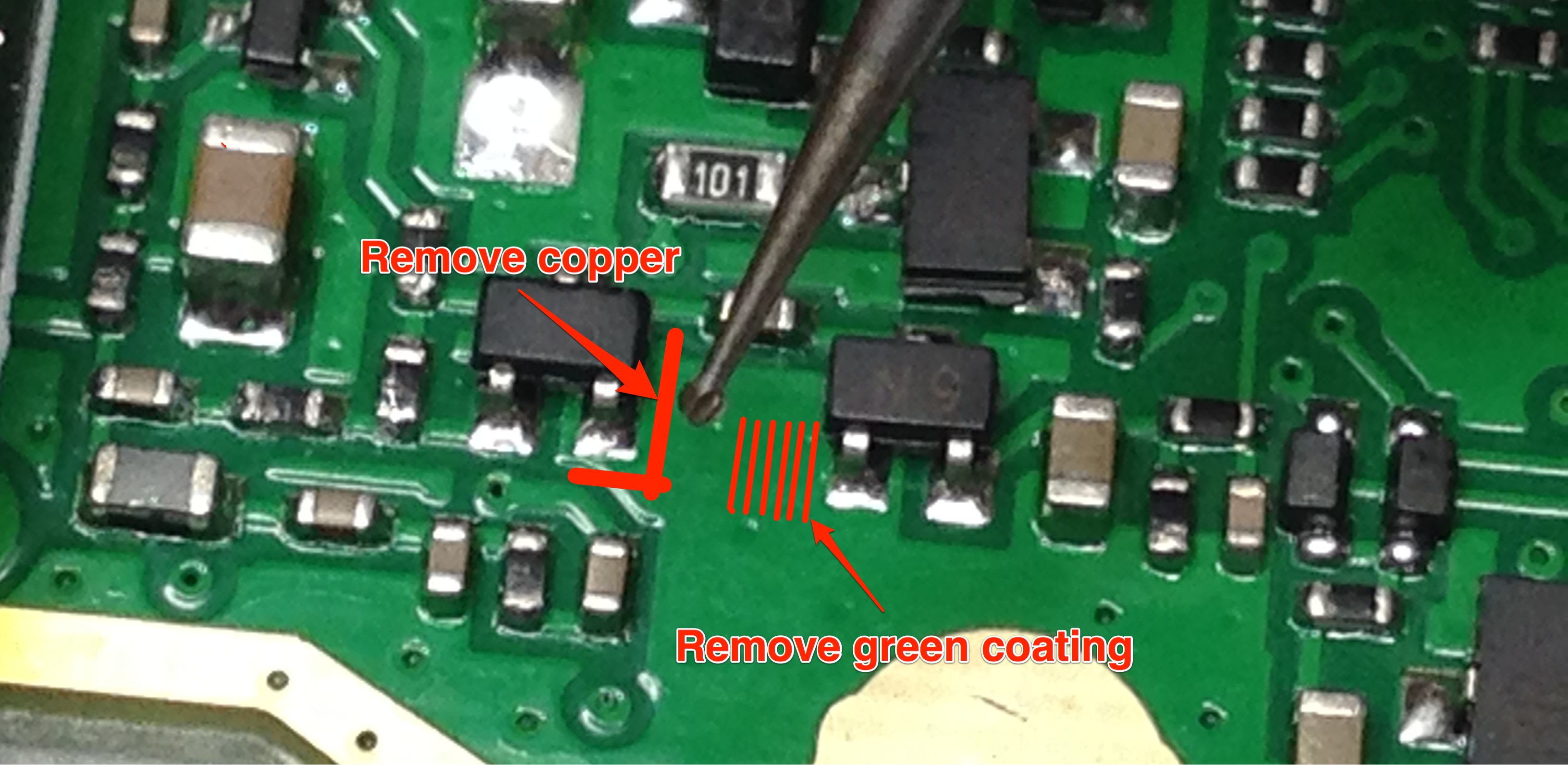
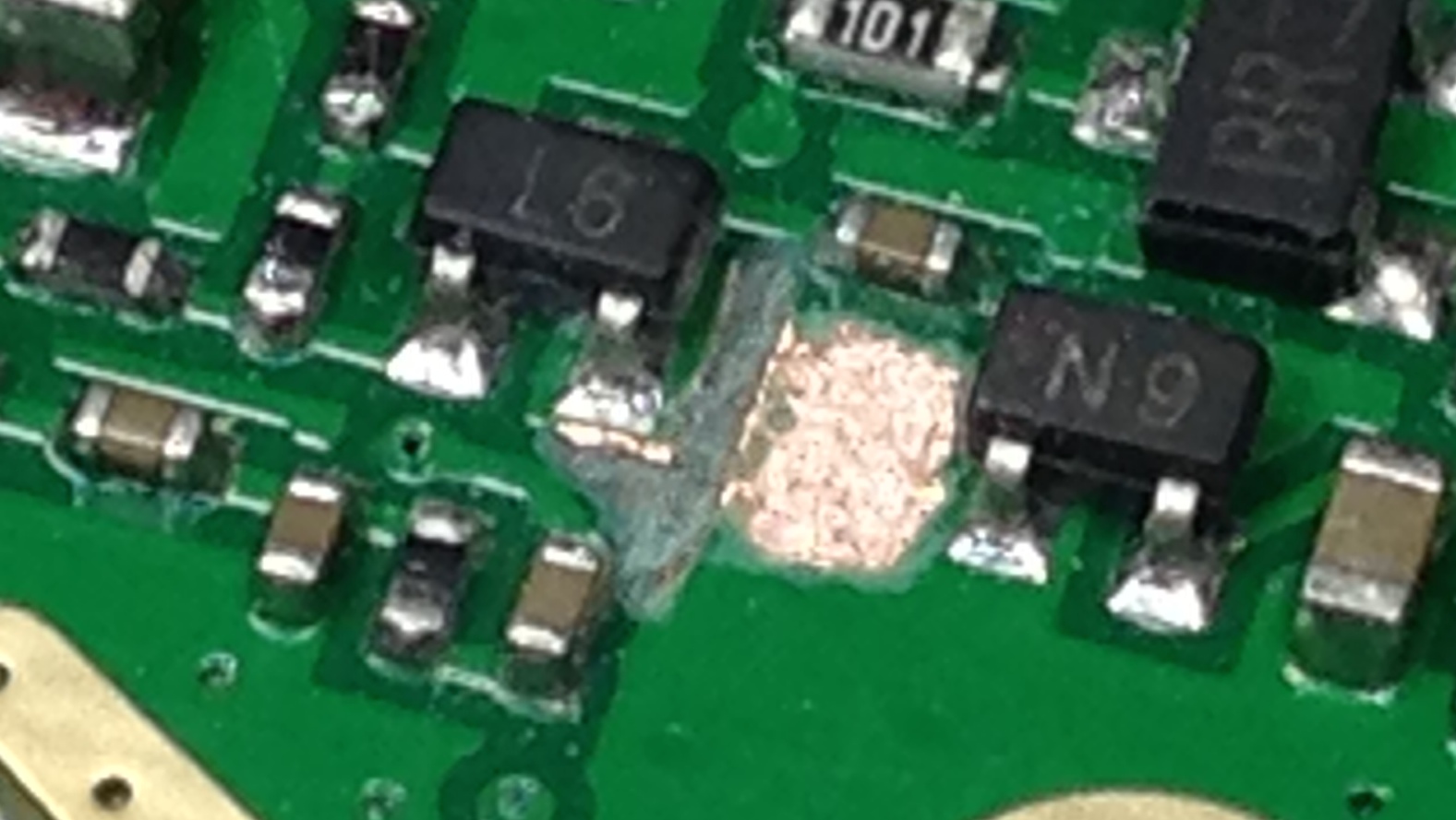
Step 3: Disconnect Emitter of Q17 Take a (very very) small drillbit and carefully disconnect the emitter of Q17:
The end result should look like this:
**Step 4: Add 560 Ohm resistor **Use a very small soldering iron tip and small tweezers or toothpick put the 560 (or 680) Ohm resistor in place:
In my case, the 560 Ohm resistor gave a bit too much amplification. For a bit more modest result, choose 680 (like Remco did), or anything up to 1k Ohm.
Step 5: Remove C135 and disconnect L44 Using the small tip of your soldering iron, heat up and wipe down on C135 to remove it. Take care to not hit other components, repairs will be almost impossible. Use the small drillbit to disconnect L44 by cutting the little trace between C137 and L44:

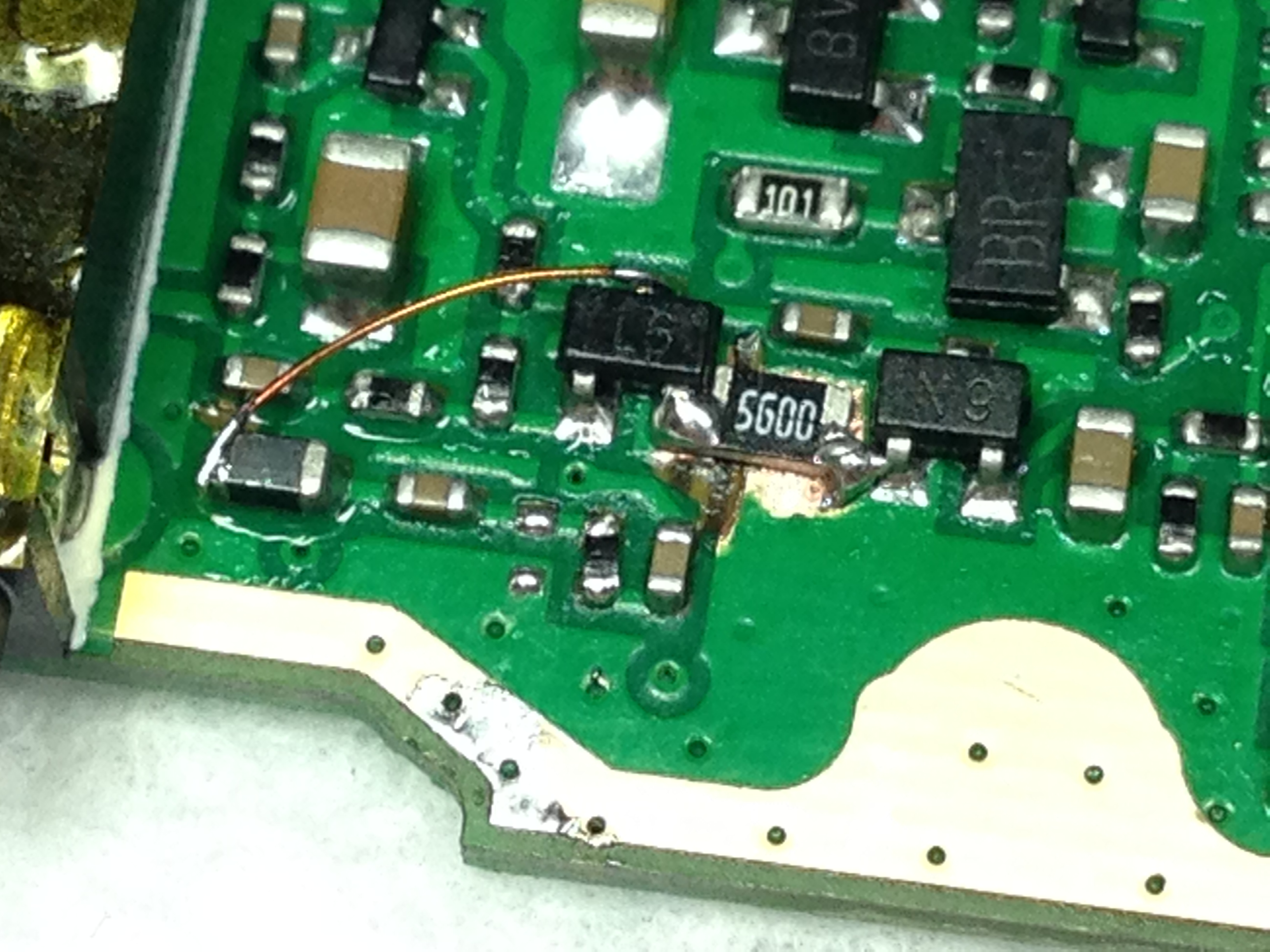
**Step 6: Connect Q17 to L44 **Take a small piece of enamel coated wire, strip 2mm at the ends and connect the collector of Q17 to L44:
Step 7: Close it up Put your radio back together. Don't forget to solder the antenna connector and backlight connections I mentioned in step 1.
When snapping the PCB back into the case, make sure that the rubber of the PTT button does not fold behind the PCB board. Make sure the rubber is nice and flat after inserting the PCB, like this:

Have fun with your new and improved modulation!
73, Rolf.