Measuring Coax Length and Loss
 Ever wondered how well your 50Ω coaxial cable is working? If you have a reasonably fast oscilloscope, preferably up to 100MHz and a signal generator which can generate short bursts, you can measure not only the length of your cable, but also the return loss at a certain frequency. From that, we can learn the attenuation of the cable.
This blog post describes the classic time domain reflection measurement using the following setup:
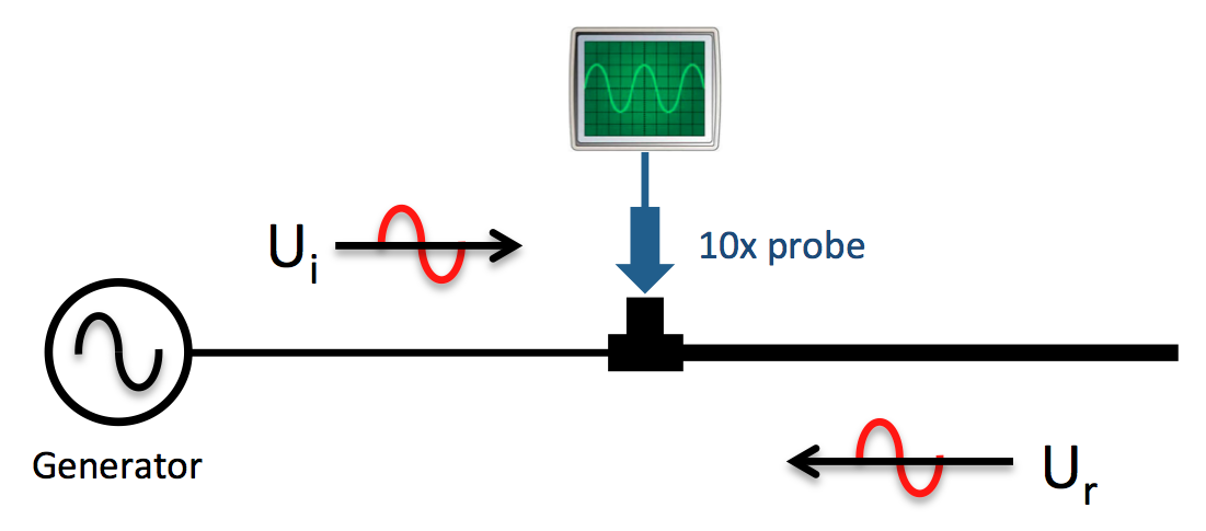
When the wave travels through the cable and back, it encounters resistance and inductance of the copper, and capacitance towards the shielding. If we can measure the returning waveform, we can say something about the cable loss.
To measure $latex U_i$ and $latex U_r$ we need to use a 10x signal probe so that we influence the signal as little as possible. If we would use a 1x signal probe, the load of the probe will make it look like our cable has quite a bit of loss. In reality, it will be the probe that is influencing the measurement.
It takes the signal a certain time to travel through the cable. In a vacuum, the signal travels at the speed of light. In a cable, the signal actually travels slower. Different cables have different speeds. The manufacturer of the cable provides this speed as a factor relative to the speed of light, called the "velocity factor". If we know the velocity factor of the cable, and the time the signal took to return, we can say something about its length.
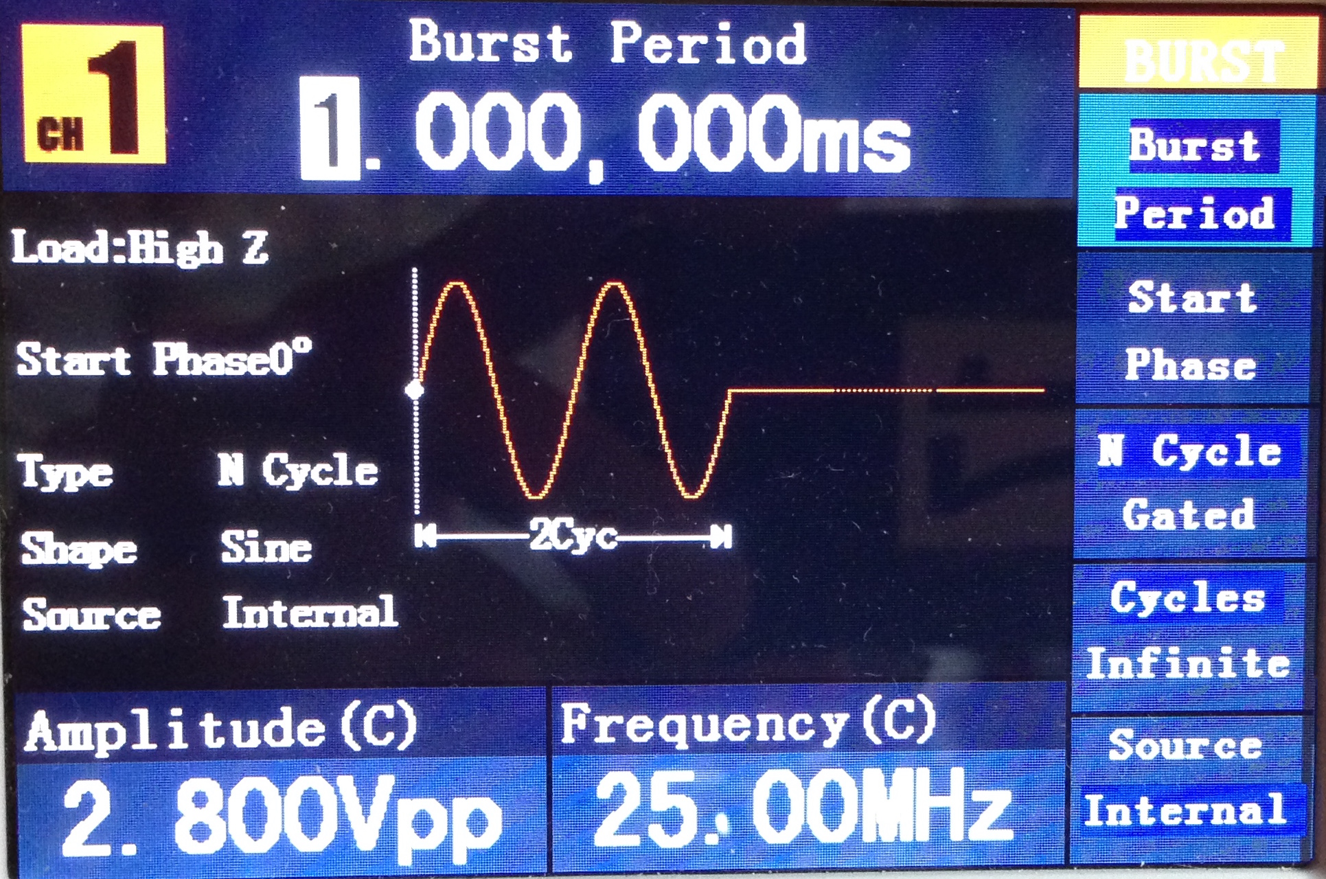
I'm using an OWON AG2052 function generator, and have set it up to generate a "burst". A 25MHz sinewave, 2 cycles. The voltage is not really important, anywhere from 1 to 5 Volts makes the measurement comfortable, well above the noise floor.
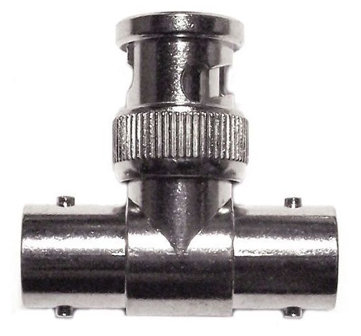
The signal generator is connected through an RG58 cable and a BNC T-connector to the coax we're testing, in this case a few meters of Ecoflex 15.
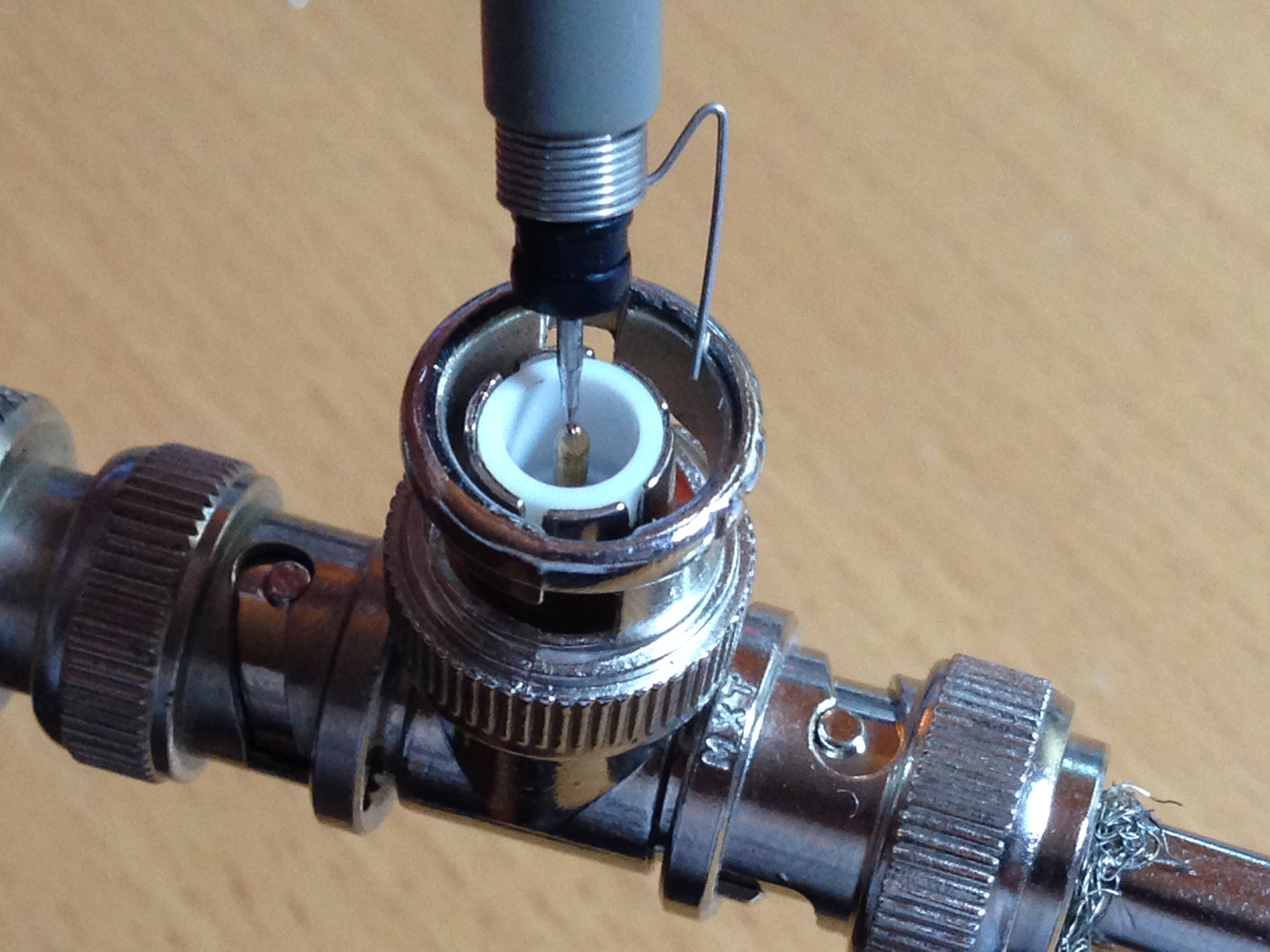
Remember those funny little springy things you received with your new 10x 100MHz probes? This is a nice example of how to use them:
If everything went well, you should see $latex U_i$ and $latex U_r$ on your oscilloscope screen. To make an accurate measurement, stretch them out big enough so they just fit the screen of the scope. Since I'm measuring the peak voltage, I don't need the lower part of the wave. Using your scope like this makes better use of your A/D converter resolution, and uses more pixels on the screen, which means better accuracy.

Cursor A and B are on the top of the second sine of $latex U_i$ and $latex U_r$. I could also have used the first, it doesn't really matter. The first sine is higher because of a little overshoot in the generator. We see that $latex U_{i (peak)}=654mV$ and $latex U_{r (peak)}=578mV$. To calculate the loss from these two voltages, we use the formula we found for calculating return loss from the reflection coefficient $latex \Gamma$ (gamma):
$latex RL_{(db)}=-20 \times \log_{10}\left(\Gamma \right)$ where $latex \Gamma =\frac{U_r}{U_i}$
Which means that in our case:
$latex RL_{(db)}=-20 \times \log_{10}\left(\frac{0.578}{0.654} \right)=-1.073dB$
We're interested in attenuation, the cable loss one-way, so we need to devide the return loss by two:
$latex \frac{-1.073}{2}=-0.54dB$
This attenuation is meaningless without knowing the length of the cable. To be able to calculate the length, we must know how fast the signal is traveling in the cable. According to the manufacturer, the velocity factor of Ecoflex 15 is 0.86. This means that a signal in this cable travels at 0.86 times the light speed:
$latex 299,792,458 \times 0.86=257,821,513.9:^m/_s$
The cursors A and B are 270nS apart. This means that the signal traveled
$latex 257,821,513.9 \times 270 \times 10^{-9}=69.61, m$
This is of course twice the length of the cable, so our cable is 34.8 meter long.
Now that we know the length and the loss of our cable, we can compare it with the manufacturer's specifications. The specifications of Ecoflex 15 say that the typical attenuation is 0.86dB per 100m at 10MHz, and 1.96dB per 100m at 50MHz. Lets assume that the attenuation is linear with the frequency between those two. The attenuation on 25MHz should be approximately 1.3dB per 100m.
We have a cable of 34.8 meter with 0.54dB attenuation, so per 100 meter that would be:
$latex \frac{100}{34.8} \times -0.54=-1.5,dB$
That's about 15% worse than the specification, but this can be easily explained by inaccuracies in our measurement, the resolution of the oscilloscope, and loss in cables and plugs. When repeating this measurement on my setup it's easy to see variations of 20% in the results.
What if your generator is slower When your generator can not do short bursts, or can't generate a high enough frequency, you can at least measure the cable length by sending a square wave down the line. This is the most common measurement to do, but doesn't give you much information about the attenuation on a certain frequency. The frequency of the square wave does not matter much, as long as the edges have a decent rise time.
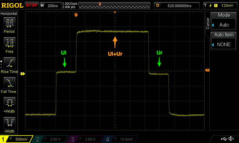
With this measurement you see $latex U_i$ on the left, then a period where the reflected $latex U_r$ is added to $latex U_i$, and then the last part of the $latex U_r$. The length of the first "Step" is the length of your cable, and the difference between $latex U_i$ and $latex U_r$ is your DC resistance.
Another possibility is that your generator can generate a burst, but not short enough. You can then still do both the return loss and cable length measurements, but it will look a bit different.

Here, the middle section where $latex U_i$ and $latex U_r$ are added should not be interpreted in any way. Depending on the length of the cable, and the phase of $latex U_r$ you can even see a lower signal here, where $latex U_r$ cancels out $latex U_i$. Only use the first and last parts of the signal,indicated with $latex U_i$ and $latex U_r$ above.
**Gotchas: **Pay attention to more than one reflection: If there is more than one reflection, your generator is not the same impedance of the cable. I made the mistake of adding a 50Ω terminator at the generator side. But since the generator was already 50Ω, I created a 25Ω impedance, which reflected $latex U_r$ and sent it back into the cable.
Also make sure you always measure an open ended cable. If an antenna is connected, the reflection measurement will work, but the return loss can not be determined. After all, the antenna is made to dissipate energy, and we don't know how much energy is lost in the cable, and how much is lost in the antenna.
Have fun experimenting, Rolf
P.S. The formulas in this article are rendered by the WordPress LaTeX plugin, and I used the codecogs equations editor to edit and preview them.