Designing a Fox-hunt antenna
 Many years ago, I used to do some radio fox hunting with cars. Usually these hunts are at night to make it more exciting, and can be great fun. As I got older I lost interest and moved on to other things. But last year, I decided to have a go at a popular balloon fox hunt on 144MHz. This is quite a large scale and professionally organized fox hunt by Dutch Radio Amateurs.
Because of the totally different setup and frequency I decided to join a few recreational 144MHz (2 meter) fox hunts to get the hang of it. If you like to play with radios and walk in the woods, this is your thing. Lots of small transmitters hidden in the bushes on random frequencies for you to find.
Last year I used a borrowed receiver and antenna, and this year I decided to build a Foxbox receiver kit.
After building the receiver, the age-old discussion among radio amateurs began: What antenna to use? I had a discussion with Remco who just designed his own Moxon antenna using the 4nec2 antenna modeler and optimizer. He convinced me to use this software in order to prevent building a lot of failing antennas and not being sure why they fail. So that's what I did.
The 4nec2 software comes with a bunch of example antennas for you to play around with. The antenna I borrowed last year was a 2 element antenna based on a Log Periodic Dipole Array antenna. It worked fine and I had fun with it so I decided to model an antenna like that. (Also because I'm hard-headed and just copying Remco's Moxon would not lead to interesting discussions).
Step 1: Getting basic dimensions of an LPDA The first thing I needed is a basic, ballpark approximation of a working LPDA antenna for 144MHz so I could get used to the 4nec2 modeling software. I used ON4AA's Log-Periodic Dipole Array calculator to get an idea of the basic dimensions.
I noticed that the length of the first and largest element of the antenna is always 1041 mm, no matter what taper or relative spacing I chose as input. Good news, because that means that the antenna only has a few parameters to change when optimizing in 4nec2, see below.
Step 2: Getting the design into 4nec2 So here is where the struggle starts. As I am a Mac user and the 4nec2 software is Windows only, I installed it on a Linux Mint virtual machine running under Wine without problems. The terminal window will log errors but you have to put your OCD aside for a moment and ignore those.
For the LPDA antenna itself the struggle was not that bad, as I found an example file and was able to change that around to learn how 4nec2 works. I'll spare you the details. Just remember that you want to use the new NEC editor (Main Window, Settings → NEC Editor (new)).
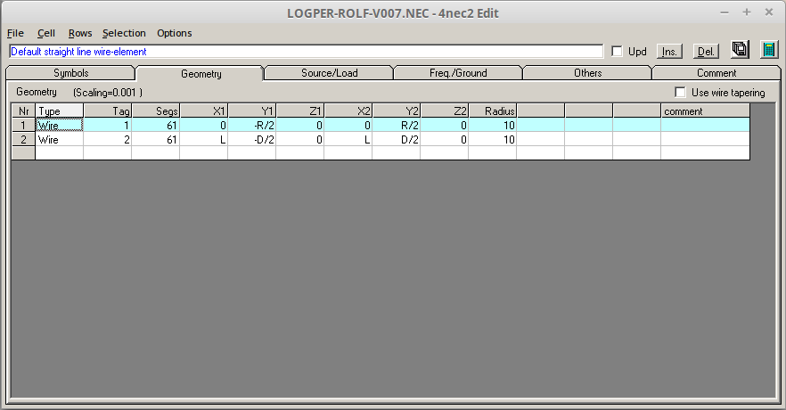
Here you see the two wires of my LPDA antenna. As you can see, each line has a start (X1,Y1,Z1) and end point (X2,Y2,Z2) in 3D space. Ignore the funny formulas in the screenshot for now. A counter intuitive thing for me was that lines are made out of "segments". 4nec2 cryptically complains about too few and too much segments, and you have to choose a number accordingly.
Another important thing to learn about 4nec2 is that you don't "connect" a source to your antenna. Rather, you choose a segment of a line which will then act as a current or voltage source (current source is the recommended default). This is why if you want to have your feed point in the middle of a wire, you need to choose an odd number of segments. In my design, both wires are 61 segments, and the feed point on both wires is on segment 31 (the middle segment of each wire).
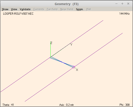
Connecting the two wires of the antenna is done using a transmission line, with a twist (literally). We connect segment 31 of both wires with a transmission line, and chose a negative impedance. This causes the transmission line to "twist" in your geometry window, and you should see something like this:
Step 3: Changing the NEC file for optimization 4nec2 contains an optimizer which can optimize certain characteristics of your antenna by iterating values. If you hard-coded the X,Y and Z values of the lines, the optimizer can not change the design. To be able to use the optimizer, I chose to have variables for the length of the boom (L), length of the driving/smallest element (D), length of the reflecting/longest element (R) and impedance of the transmission line (TRI). This explains the funny values for the X,Y,Z coordinates in my file. The variables can be found on the "Symbols" tab of the NEC editor.
Step 4: Optimize! Close the Editor window, and in the main window, select Calculate -> Start Optimizer. The optimizer parameters can be a bit confusing. Choose the "Optimize" function in the drop-down top left, and leave the Option set to "default". Below the text "Weighting factors in %" you'll see 7 text fields. Set them all to 0, except for "F/B", the Front-to-back ratio. That should be set to 100, As we are only interested in maximum directivity.
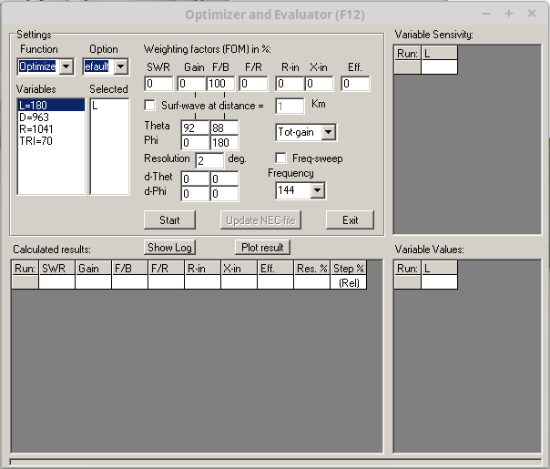
Now that we have told 4nec2 what we want (max F/B), we need to tell the optimizer which variables it can play with. In this simple design, you could select all variables by clicking on them, which moves them to the "selected" column. I tried, this does not lead to practical results and takes a bit of time depending on the speed of the computer. All open geometry or 3D view windows will live-update with the calculations. This looks really cool but things go faster if you close them.

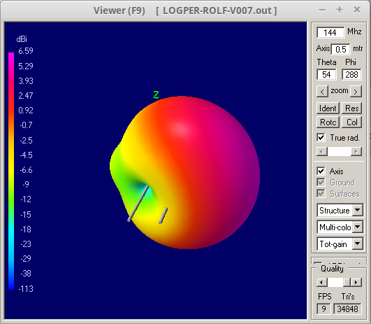
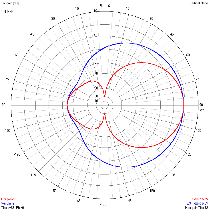
After a bit of playing with the optimizer, I got to the following radiation pattern:
Step 5. Build and field test. At this point, the software will have tried tens, if not hundreds of different antenna variations you didn't have to physically build. But now that we are "certain", we can build the antenna. The boom is aluminum profile, the radials are made of measuring tape so they can be folded, and the handle is a broomstick:
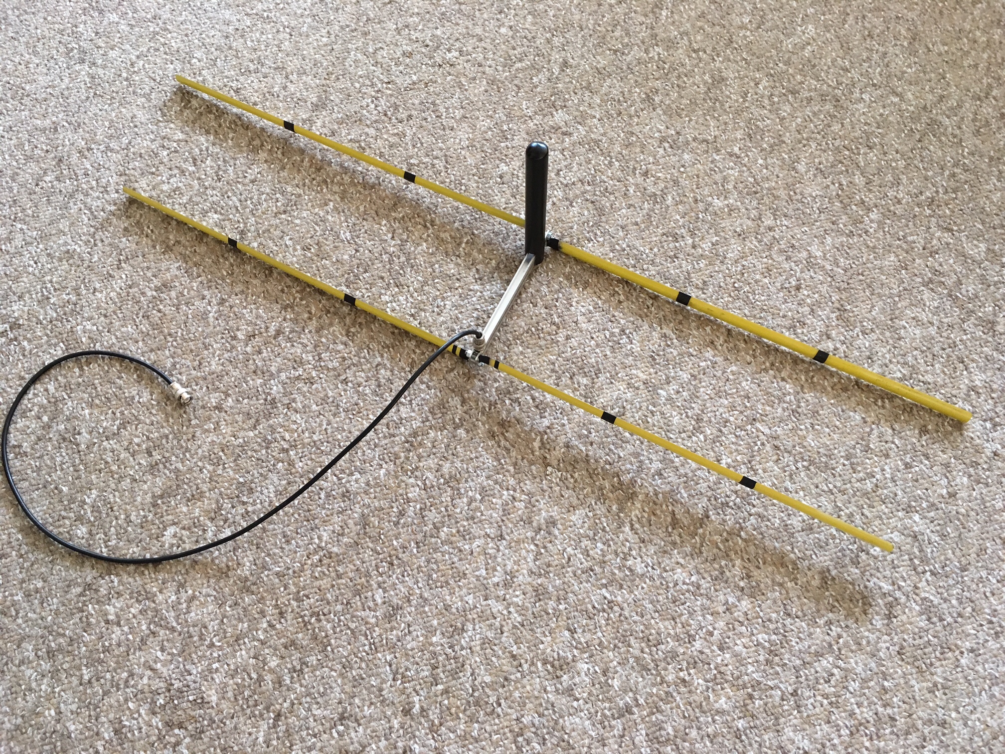
I've spent extra effort to make sure the dimensions are as close to the simulation as possible, to maximize the chance that it actually works as designed.
I did a field test together with my dad, where we used a Baofeng handheld (yes that one) as a "fox", taking turns in hiding it for the each other. The tests went "sort of okay", but I noticed that it sometimes felt as if there was not one peak straight in front of the antenna, but rather two peaks left and right. This got me worrying about the accuracy of the build or the simulation. I even started doubting impact of impedance mismatch and cable length. When we got home however, I checked and saw that the 4nec2 software actually predicted this in a different diagram:

It turns out, that if the antenna is held horizontally, and the transmitter antenna is a vertical, the whole system behaves exactly as simulated, with the antenna being almost "deaf" right in front of the boom. Solution: Turn the antenna vertical or horizontal while hunting to find the maximum signal. We noticed that without being able to see the radio, I could exactly match the angle of the vertical antenna. My dad hid the fox in a tree at 45 degrees, and without seeing or knowing it I matched the angle of the antenna perfectly.
Step 6. Game on! Just today I tried the whole setup in an actual fox hunt with 24 foxes (yes that many). I was very pleased with the performance of the antenna, and I found 14 of the foxes. With a bit of practice and experience, I'm sure I can improve to find more foxes next time around.
And last but not least, here is the 4nec2 file for you to play around with:
[sourcecode language="text" padlinenumbers="false"] CM Log Periodic Dipole Array for 2m fox hunting CE SY L=180 'Boom length SY D=963 'Driver length SY R=1041 'Reflector length SY TRI=70 'Transmission line impedance GW 1 61 0 -R/2 0 0 R/2 0 10 GW 2 61 L -D/2 0 L D/2 0 10 GS 0 0 0.001 GE 0 GN -1 EK EX 6 2 31 0 1 0 0 TL 1 31 2 31 -TRI 0 0 0 0 0 FR 0 20 0 0 144 0.1 EN [/sourcecode]
Have fun!