Interdigital Bandpass for RTL2832U Receiver
 Building a receiver for a voice repeater system in this area I set up a thumbsat receiver connected to a Raspberry Pi. The receiver is part of the repeater system to widen it's receiving range. However, the performance turned out not to be too optimal. I guessed that the GSM and Wifi signals around here could cause the RTL2832U to overload, so I decided to build an intedigital bandpassfilter using Ajarn Changpuak's excelent interdigital bandpass filter calculator.
Because size was an issue and the GSM and Wifi bands are not very close to the receive frequency, I decided on a 2 element filter with 8MHz passband and 0.2dB ripple. Playing with the calculator got me the following filter dimensions:
[sourcecode gutter="false"] Length interior Element : 54.54 mm or 2.147 inch Length of end Element : 54.72 mm or 2.154 inch Ground plane space : 20 mm or 0.787 inch Rod Diameter : 4 mm or 0.157 inch End plate to center of Rod : 10 mm or 0.394 inch Tap to shorted End : 1.41 mm or 0.055 inch
**** Dimensions, mm (inch) ****
End to Center Center-Center G[k] Q/Coup
0 0.00 (0.000) 1 10.00 (0.394) 35.97 (1.416) 1.038 0.714 2 45.97 (1.810) 0.00 (0.000) 0.675 1.738 3 55.97 (2.204)
**** Box inside dimensions **** Height : 59.00 mm or 2.323 inch Length : 55.97 mm or 2.204 inch Depth : 20.00 mm or 0.787 inch [/sourcecode]
As I discovered later, forgetting to refresh the calculations one last time resulted in incorrect dimentions (yes, the dimensions are incorrect in the list above).
I built the filter with blank PCB sheet and brass rods I had lying around. The first version looked like this:
Without the top screwed it performed beautifully, but that turned out to be coincedence. Closing the filter up showed some strange characteristicts and the passband was on a much lower frequency.
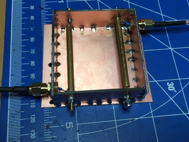
I used my miniVNA Tiny to look at the characteristics while fiddling with it. To make it work I used copper shielding of an RG213 cable to close the filter properly, connected the inside and outside copper on the PCB, and added two solid wires to create a stronger coupling and changing the frequency. A bit unconventional and structuraly unsound, but it worked, and it ended up looking like this:
| [ ](img_6400-small.jpg) | [ ](img_6413-small.jpg) |
| [ ](1270-mhz-bandpass-s12.png) | [ ](img_6489-crop.jpg) |
It still felt strange that the filter does not behave as designed so I returned to Ajarn Changpuak's page to re-check my calculations and it turned out to be incorrect. The correct dimensions would have been:
[sourcecode gutter="false"] Length interior Element : 54.53 mm or 2.147 inch Length of end Element : 54.72 mm or 2.154 inch Ground plane space : 20 mm or 0.787 inch Rod Diameter : 4 mm or 0.157 inch End plate to center of Rod : 10 mm or 0.394 inch Tap to shorted End : 1.78 mm or 0.070 inch
**** Dimensions, mm (inch) ****
End to Center Center-Center G[k] Q/Coup
0 0.00 (0.000) 1 10.00 (0.394) 32.98 (1.298) 1.038 0.714 2 42.98 (1.692) 0.00 (0.000) 0.675 1.738 3 52.98 (2.086)
**** Box inside dimensions **** Height : 59.00 mm or 2.323 inch Length : 52.98 mm or 2.086 inch Depth : 20.00 mm or 0.787 inch [/sourcecode]
Aha. This explains it. After re-calculating, the rods should have been closer together and the tap to the shorted end should have been further from the casing. I guess I have to re-do this filter with the correct dimensions some time. After this adventure I'm fairly confident that I can get it to behave nicely.