1N4148 diode as RF switch

Aren't diodes rectifiers?
Yes and no. The most basic operation of a diode is to pass current in one way, and block it in the other. But when the diode passes DC current, the internal capacitance lowers, and RF resistance will drop to around 1 Ohm. If you can separate the DC and RF currents, you can switch RF with DC. Most, if not all modern transceivers use PIN diodes to switch the antenna between the internal transmitter and receiver components.
PIN or PN diode?
A P/N diode like the 1N4148 only has P and N doped regions. A P/I/N diode has three semiconductor regions with different doping. The I region in a PIN diode makes it a bad/slow rectifier but it a great RF switch, see the provided wikipedia link for more info.
Enough talk. Let's go. In this case I want to know how a PIN diode like the BA389 compares to an 1N4148 when used for switching RF signals on 145 MHz and 435 MHz. I decided to use my MiniVNA Tiny and the following circuit to do the measurements:
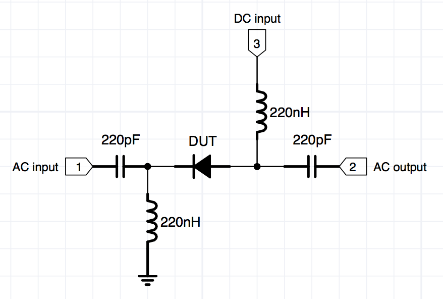
The output of the MiniVNA Tiny is connected to a 10 dB attenuator, reducing the -6 dBm (0.251 mW) output of the VNA to -16 dBm (0.025 mW) hoping to reduce signal leaking around the diode (less signal, less leakage). The output of the attenuator is connected to the AC input on the left side of the schematic.
The input of the MiniVNA Tiny is connected to the output of the schematic. Yes, the RF travels through the diode the "wrong way", against the DC current. This is not an error.
The DC input of the circuit is connected to a variable resistor, a multimeter and a power supply to be able to vary the current through the diode (DUT) from 0.001 mA to 20 mA.
 |
 |
Before measuring diodes I callibrated the whole setup by having vnaJ measure the "OPEN" characteristics with everything connected but with the diode removed. Then, I soldered a wire in place of the diode and had vnaJ measure the "CLOSED" characteristics. I saved this callibration dataset and used it throughout all other measurements.
Then, I soldered a 1N4148 in place and measured RF Transmission Loss for a number of currents between 0 and 15 mA. Then I did the same for the BA389. After a bit of fiddling with Excel I produced the following graph of the results:

The verdict:
The results are actually not that bad for the 1N4148. It shows behaviour and comparable linearity to the BA389 PIN diode. The attenuation of the 1N4148 leaves to be desired: -25,5 dB attenuation compared to -30.3 dB of the BA389 on 145 MHz. On 435 MHz the difference is a bit bigger: -14.1 dB vs -20.1 dB for the BA389. All in all, the 1N4148 is roughly 6 dB more "leaky" than the BA389.
So a 1N4148 actually works as an RF switch, if you are on lower frequencies and don't mind that it only attenuates -25,5 dB. If you need high performance RF switching with high isolation, particularly at frequencies above 200 MHz or so I think you're better off selecting a proper PIN diode.
Here are the 1N4148 and the BA389 graphs from the MiniVNA Tiny. The graph for the 1N4148 is an earlier one where I didn't have the extra shields. The dip in the 200MHz range is caused by the measurement jig itself. Mind the vertical scales, they don't match. Blue line is Transmission Loss:
 |
 |